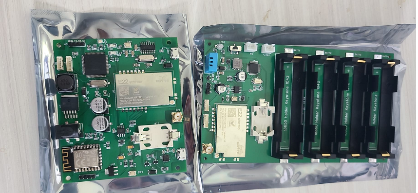
BeetleGuard
Scalable LoRa monitoring system handling 250 devices/hub for real-time environment tracking. FreeRTOS task architecture with dedicated sensor, radio, and cloud sync tasks. 5 hubs active in production.
STM32LoRa SX1278FreeRTOS
SPIUARTAWS IoTCloud Dashboard
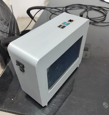
IoT Payphone System
RFID-authenticated payphone for student GSM calling — 2500+ units deployed. Raspberry Pi handles cloud sync, usage logging, and a remote dashboard for parent and admin access.
Raspberry PiRC522 RFIDGSM Module
SPIUARTREST APIData ExportCloud Dashboard
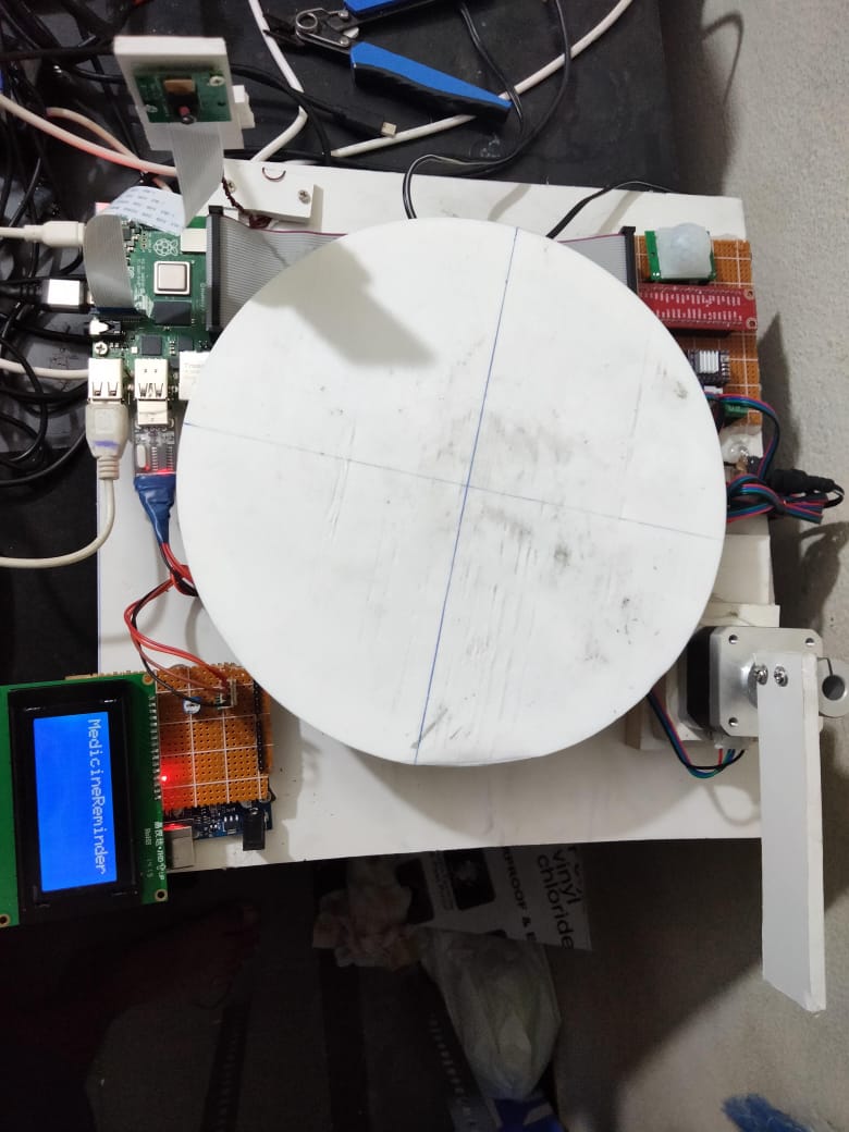
Medicine Reminder System
Automated medicine reminder and dispenser using Raspberry Pi. Rotating platform positions the correct compartment at dispense time, with LCD alerts and scheduled reminders for patient compliance.
Raspberry PiLCD DisplayMotor Control
GPIOSchedulerAutomation
Oxygen Therapy System
SpO₂-driven closed-loop oxygen flow control on STM32. Independent high-priority alarm task, hardware watchdog, and NVM-backed alarm state persistence for safety-critical medical operation.
STM32MAX30102 SpO₂Flow Control Valve
ADCMedical AlarmsWatchdog
Standalone Diagnostic Analyzer
Standalone biochemical analyzer for urine metabolite identification. Optical sensor array driven by STM32 ADC with calibration coefficients stored in flash. Outputs formatted diagnostic reports over UART to a local printer.
STM32Optical SensorsADC
UARTStandalone UIReport Generation
Patient Vitals Monitor (BLE)
Ultra-low-power vital signs monitor on Si Labs BGM220. Custom GATT service packs HR, SpO₂, and NTC temperature into a single characteristic notification. Sub-500nA sleep current achieved via load-switch isolation and EM4 deep sleep.
Si Labs BGM220BLE 5.0MAX30102
NTC ThermistorGATTMobile App
ULP BLE Temperature Logger
BLE temperature logger on Si Labs BGM220 with nano-ampere sleep current. Removed all pull-up resistors on sleep-sensitive nets; replaced with software-configured internal pull-ups that disengage in EM4 sleep. Energy harvesting enables indefinite coin-cell operation.
Si Labs BGM220BLE 5.0Energy Harvesting
nA Sleep CurrentLow Power ModesSPI
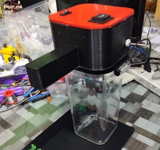
Food Sanitization Machine
Standalone food sanitization unit with timed processing cycles. STM32 drives relay-controlled actuators via a state machine with door-interlock safety — cycle cannot start unless interlock is closed. 3D printed enclosure with integrated chamber.
STM32Relay ControlTimer Logic
HMIAutomationSafety Interlocks
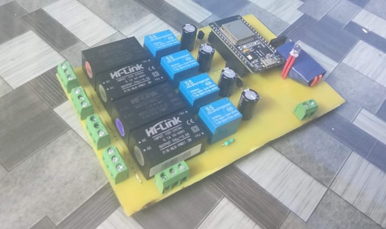
Industrial IoT PLC Interface
ESP32-based bridge between legacy PLC digital I/O and MQTT cloud. Reads RS485/Modbus registers from the PLC and publishes to AWS IoT; subscribes to control topics and drives relay outputs. Hi-Link AC-DC modules provide mains-isolated 5V on-board.
ESP32RS485 / ModbusDigital I/O
MQTTPLC SignalsCloud Integration
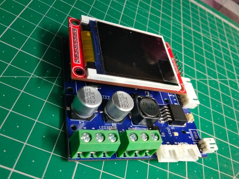
Industrial IoT Data Logger
Multi-input data logger supporting RS485/Modbus, 4–20mA (250Ω shunt + ADS1115), and 0–10V inputs. On-board TFT shows live channel readings; ESP32 publishes to MQTT broker with QoS 1 for guaranteed alarm delivery.
ESP32RS4854–20mA
0–10V ADCADS1115MQTTCloud Sync
Therapeutic Gas Monitor
Standalone clinical gas monitor measuring nitric oxide concentration via electrochemical sensor with custom analog front-end. Safety-critical alarm thresholds with fail-safe firmware architecture for reliable medical operation.
STM32Electrochemical SensorADS1115
MCP1525Trans-impedance AmpMedical Alarms
ULP Women Safety Device
nRF52840-based safety wearable with gesture-triggered BLE emergency alert. Accelerometer interrupt wakes from deep sleep; firmware validates gesture pattern before alerting to prevent false triggers. Load-switch gating of all peripherals during idle.
nRF52840BLE 5.0Accelerometer
Ultra Low PowerEmergency AlertsMobile App
Smart Wrist Wearable
Si Labs BGM220 wearable combining MAX30102 vitals and CCS811 air quality in one BLE GATT service. I²C bus shared between sensors with interrupt-driven scheduling to prevent bus contention. Single characteristic packs all sensor data to minimise connection events.
Si Labs BGM220BLE 5.0MAX30102
CCS811 Air QualitySensor FusionMobile App
ECG Monitoring System
nRF52840 acquiring ECG at 500 SPS via AD8232 + ADC. Lead-off detection (LOD± pins) prevents false arrhythmia detection from disconnected electrodes. 0.05Hz high-pass firmware filter removes baseline wander without distorting QRS. MAX30100 on I²C runs interrupt-driven alongside timer-based ECG sampling.
nRF52840AD8232MAX30100
DS18B20BLE 5.0ADCSignal Conditioning
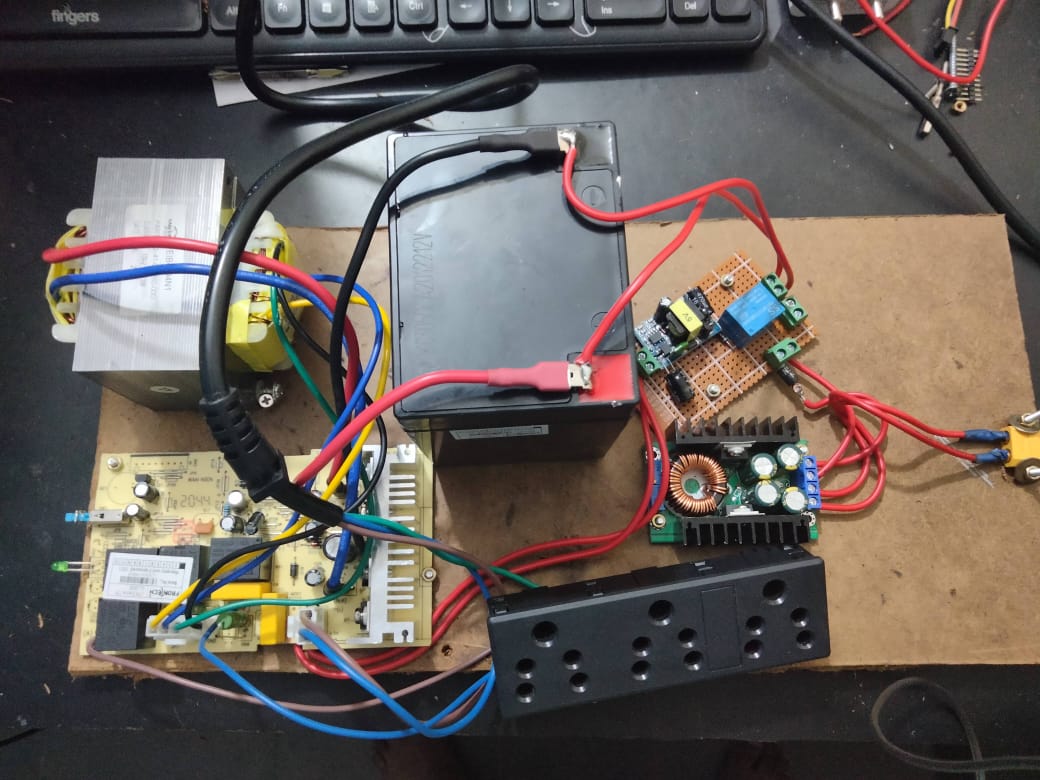
Solar Inverter Prototype
Prototype solar inverter with transformer-based AC conversion, 12V battery input, relay-controlled switching, and DC-DC boost stage. Designed to validate inverter topology and control logic before custom PCB.
Power ElectronicsTransformerRelay Control
DC-DC BoostBatteryInverter
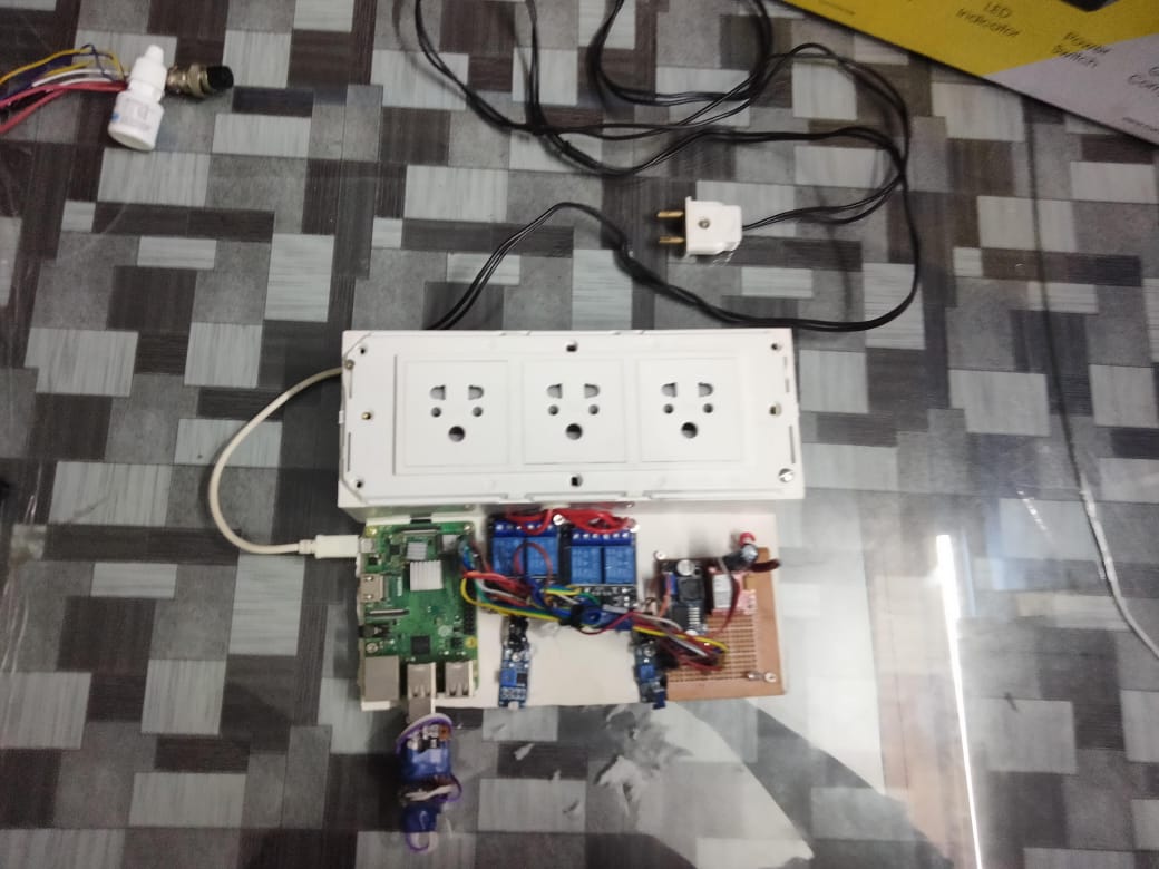
Industrial Home Assistant
Raspberry Pi-based home automation controller driving mains-powered outlets via relay board. Remote control and scheduling over local network with GPIO-driven relay switching for AC load management.
Raspberry PiRelay ControlGPIO
AC LoadHome AutomationNetwork Control
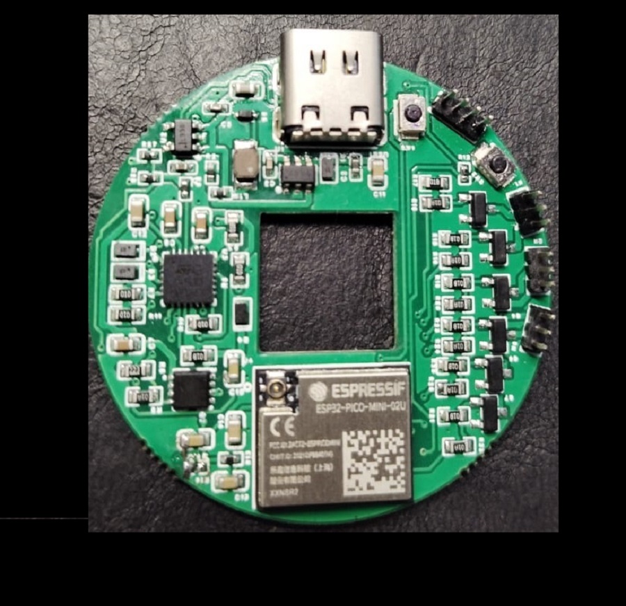
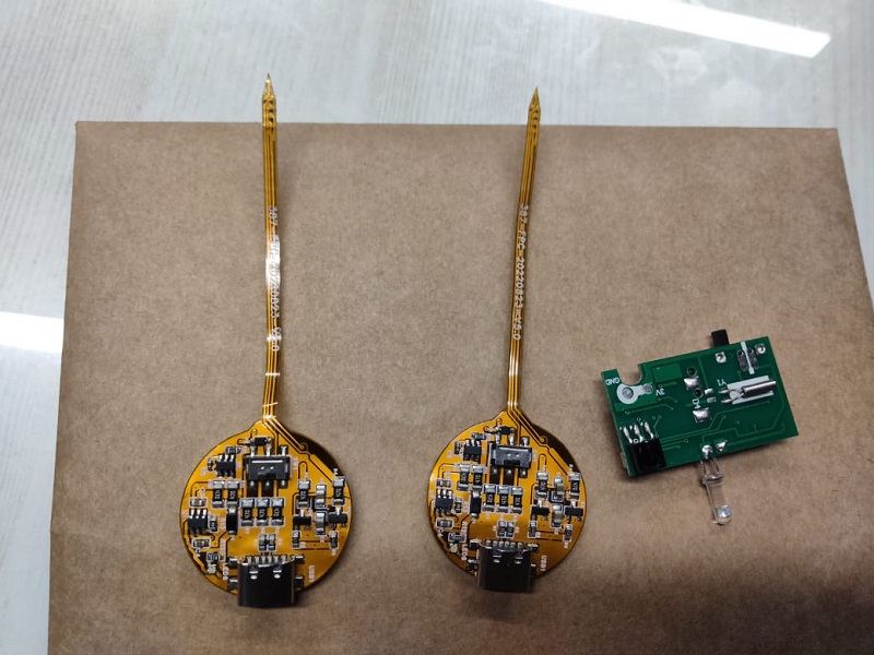
Modern Flame Diya
Custom KiCad PCB with ATtiny driving WS2812 LEDs in a realistic flame animation via PWM. Touch-capacitive control with three brightness modes. Circular gold PCB with upright flame-shaped LED strip — fully self-contained with USB-C charging.
Custom PCBATtinyPWM
Touch SensingWS2812 LEDsKiCad